News
What Are Pipeline Pumps and How Do You Choose the Right One?
What Is a Pipeline Pump and What Role Does It Play in Fluid Systems?
A pipeline pump is a mechanical device specifically engineered to move fluids — liquids, slurries, or occasionally gases — through a pipeline system by adding energy to the flowing medium, increasing its pressure and sustaining its velocity over long distances and through significant elevation changes or resistance losses. Unlike general-purpose pumps that may be deployed in open systems or batch processes, pipeline pumps are designed to operate inline within a continuous pressurized piping network, maintaining steady flow rates against the cumulative head losses generated by pipe friction, fittings, valves, and static elevation differences along the pipeline route. Their role is foundational in any industrial or municipal system where fluid must be transported reliably from a source to a destination through a closed conduit — whether that destination is a processing facility, storage terminal, distribution network, or end consumer.
The term "pipeline pump" encompasses a broad family of pump types differentiated by their operating principle, construction, shaft orientation, seal configuration, and the physical and chemical characteristics of the fluid they are designed to handle. Understanding what distinguishes pipeline pumps from other pump categories, and what differentiates the various types within the pipeline pump family, is the essential starting point for any engineer or procurement specialist tasked with selecting, specifying, or maintaining pumping equipment in a pipeline system.
How Pipeline Pumps Work: The Basic Operating Principle
The majority of pipeline pumps in industrial and municipal service are centrifugal pumps — devices that transfer energy to the fluid through the rotational motion of an impeller. When the impeller rotates, it imparts kinetic energy to the fluid entering at the center (eye) of the impeller, accelerating it radially outward through the impeller vanes. This high-velocity fluid then enters a progressively widening volute or diffuser casing surrounding the impeller, where the velocity head is converted into pressure head according to Bernoulli's principle. The resulting pressure differential between the pump inlet and outlet drives fluid through the pipeline against system resistance.
The relationship between flow rate, pressure head, and pump speed in a centrifugal pipeline pump is described by the pump's characteristic curve — a graphical representation of head versus flow at a given operating speed. As flow rate increases, the head developed by the pump decreases in a characteristic drooping curve. The actual operating point is determined by the intersection of the pump curve with the system resistance curve, which represents the total head required to overcome friction losses and static elevation at each flow rate. Understanding this interaction between pump performance and system characteristics is fundamental to proper pump selection, parallel pump operation, and the diagnosis of flow or pressure deficiencies in an existing system.
Main Types of Pipeline Pumps and Their Design Differences
Pipeline pumps are manufactured in several distinct configurations, each suited to different installation conditions, fluid characteristics, flow requirements, and head demands. Selecting the correct pump type is as important as selecting the correct size — a pump of the right capacity but wrong construction can perform poorly, wear rapidly, or fail prematurely in service.
Horizontal Inline Pipeline Pumps
Horizontal inline pumps are among the most widely deployed pipeline pump configurations in commercial building services, water distribution, and light industrial applications. In this design, the pump suction and discharge flanges are coaxially aligned on a common centerline, allowing the pump to be installed directly into a straight run of horizontal piping without offset connections or changes in pipe direction. The motor is mounted horizontally alongside the pump casing, connected via a flexible coupling. This configuration minimizes installation footprint, simplifies pipework connections, and makes the pump mechanically accessible for maintenance without requiring disconnection of the suction and discharge piping. Horizontal inline pumps are available in close-coupled versions — where the impeller mounts directly on an extended motor shaft with no separate bearing housing — and long-coupled versions where an independent pump shaft runs in its own bearing frame.
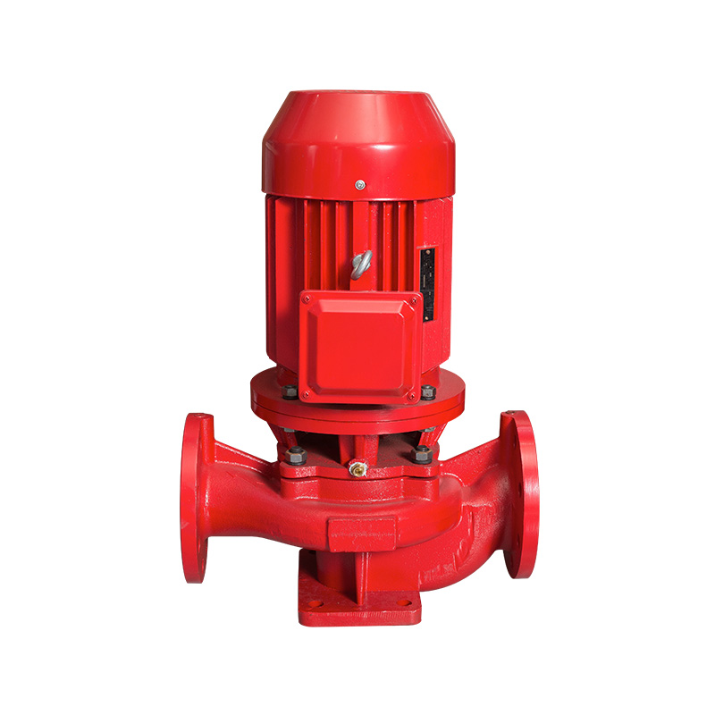
Vertical Inline Pipeline Pumps
Vertical inline pumps share the same coaxial suction-discharge flange arrangement as horizontal inline designs but mount the motor vertically above the pump casing. This orientation is particularly advantageous in space-constrained plant rooms and mechanical equipment areas where floor space is at a premium. The vertical motor position also eliminates concerns about motor bearing loading from coupling misalignment and allows the motor to run cooler by removing it from the warm air zone near floor level. Vertical inline pumps are standard equipment in HVAC chilled water and heating hot water circulation systems, domestic hot and cold water booster sets, and industrial cooling water circuits.
Horizontal Split-Case Pumps
Split-case pipeline pumps feature a pump casing divided along a horizontal plane through the pump shaft centerline, allowing the upper casing half to be lifted clear for complete access to the impeller, wear rings, shaft, and mechanical seals without disturbing the suction and discharge pipe connections. This maintainability advantage makes split-case pumps the preferred choice for large-flow, high-reliability pipeline applications in water treatment plants, fire protection systems, irrigation mains, and industrial process water circuits. Split-case pumps typically accommodate double-suction impellers — where fluid enters the impeller from both sides simultaneously — which halves the axial thrust on the shaft bearings and allows the handling of larger flow rates at lower inlet velocities, improving resistance to cavitation.
Multistage Pipeline Pumps
Where a single impeller stage cannot develop sufficient pressure head to meet system requirements — as in long-distance water transmission mains, high-rise building boosting systems, reverse osmosis feed systems, and boiler feed applications — multistage pipeline pumps stack two or more impellers in series on a common shaft within a single pump casing. The discharge from the first stage impeller feeds directly into the suction of the second stage, and so on through all stages, with each stage adding an incremental pressure increase. Multistage pumps can develop heads exceeding several hundred meters while maintaining the mechanical simplicity of a single motor-driven rotating assembly, making them far more compact and cost-effective than equivalent head achieved by staging multiple single-stage pumps in series.
Key Performance Parameters for Pipeline Pump Selection
Selecting a pipeline pump requires precise definition of the system's hydraulic requirements and the fluid's physical properties. Undersizing leads to insufficient flow or pressure; oversizing results in wasted energy, excessive mechanical stress, vibration, noise, and premature component wear. The following parameters must be accurately established before any pump selection can be made responsibly.
| Parameter | Definition | Typical Units |
| Flow Rate (Q) | Volume of fluid moved per unit time | m³/h, L/s, GPM |
| Total Dynamic Head (TDH) | Total pressure energy added by pump, expressed as fluid column height | meters (m), feet (ft) |
| Net Positive Suction Head (NPSH) | Pressure available at pump inlet above vapor pressure; must exceed NPSHr | meters (m) |
| Fluid Density / Specific Gravity | Determines actual pressure from head; affects power demand | kg/m³, SG relative to water |
| Viscosity | Resistance to flow; high viscosity reduces centrifugal pump performance | cP (centipoise), mPa·s |
| Hydraulic Efficiency (η) | Ratio of useful hydraulic power output to shaft power input | % (typically 60–88%) |
| Shaft Power (P) | Motor power required at pump shaft under specified operating conditions | kW, HP |
Among these parameters, Net Positive Suction Head (NPSH) deserves particular attention because cavitation — the formation and collapse of vapor bubbles within the pump when local pressure drops below the fluid's vapor pressure — is one of the most destructive phenomena a pipeline pump can experience. Cavitation causes intense localized pressure pulses that erode impeller vanes and casing surfaces, generates characteristic crackling noise, and can lead to catastrophic mechanical damage within a short operating period if left unaddressed. The available NPSH at the pump inlet (NPSHa) must always exceed the pump's required NPSH (NPSHr) by an adequate safety margin, typically a minimum of 0.5–1.0 m depending on application criticality.
Mechanical Seal and Bearing Configurations in Pipeline Pumps
The mechanical seal and bearing arrangement in a pipeline pump are among the most maintenance-sensitive components in the assembly, and their design significantly influences both the pump's reliability in service and the total cost of ownership over the equipment's operational life. Mechanical seals prevent process fluid from leaking along the pump shaft where it exits the casing, maintaining containment integrity and protecting the environment, personnel, and surrounding equipment from potentially hazardous or damaging fluid exposure.
Single mechanical seals — consisting of a rotating seal face mounted on the shaft and a stationary mating face fixed to the gland plate, held in contact by spring pressure — are standard in clean water and low-hazard fluid applications. For toxic, flammable, or environmentally regulated fluids, double mechanical seals with a pressurized barrier fluid between the two seal faces provide the additional containment required to meet safety regulations and prevent any process fluid from reaching the atmosphere. Cartridge seal assemblies, which come pre-assembled and pre-set from the manufacturer, have become the industry standard for most pipeline pump applications because they eliminate the risk of incorrect seal face gap setting during installation — one of the primary causes of premature seal failure in field-assembled configurations.
Pipeline Pump Applications Across Major Industries
Pipeline pumps serve as the circulatory system of industrial, municipal, and commercial fluid networks across virtually every sector of the global economy. The specific pump design, material specification, and performance rating required varies enormously between industries, but the fundamental requirement — reliable, efficient transfer of fluid through a pressurized pipeline system — is universal.
- Water supply and distribution: Municipal water authorities use large horizontal split-case and vertical turbine pipeline pumps to move treated water from treatment plants through transmission mains to elevated storage reservoirs and pressure zones, maintaining supply pressure and flow across entire city distribution networks.
- Oil and gas transmission: Crude oil, refined petroleum products, and natural gas liquids are moved through cross-country pipeline systems by high-pressure, high-capacity centrifugal pipeline pumps — often driven by large gas turbines or electric motors — with booster pump stations positioned at intervals along the route to maintain the required delivery pressure.
- HVAC and building services: Chilled water and heating hot water circuits in commercial buildings, hospitals, data centers, and industrial facilities rely on inline pipeline pumps — typically variable speed driven — to circulate temperature-controlled fluid through air handling units, fan coil units, and heat exchangers with energy-efficient flow modulation.
- Chemical and process industry: Pipeline pumps in chemical plants must handle an enormous range of fluids — from ultrapure water to highly corrosive acids, caustic solutions, solvents, and viscous polymer melts — requiring careful material selection for pump casings, impellers, shaft sleeves, and seal components to resist chemical attack and maintain safe containment.
- Fire protection systems: Dedicated fire pump sets — typically split-case or end-suction centrifugal pumps driven by electric motors and diesel engine backup units — maintain pressurized water supply to building sprinkler and hydrant systems, with performance verified against NFPA 20 or equivalent national standards.
- Agriculture and irrigation: Large-scale irrigation schemes use pipeline pumps to draw water from rivers, reservoirs, or wells and distribute it under pressure through buried distribution mains to field outlets, drip irrigation systems, or overhead sprinklers across thousands of hectares of agricultural land.
Energy Efficiency in Pipeline Pump Systems: Variable Speed Drives and System Optimization
Pipeline pumping represents one of the largest categories of industrial electrical energy consumption globally, accounting for an estimated 20% of total industrial motor electricity use in many developed economies. The opportunities for energy savings in pump systems are therefore substantial, and the primary tool for capturing these savings is the variable speed drive (VSD) — also known as a variable frequency drive (VFD) — which allows pump speed to be adjusted continuously to match actual system demand rather than operating at fixed speed and throttling flow with control valves.
The energy saving potential of VSDs in pipeline pump applications is governed by the affinity laws, which state that pump flow rate is proportional to rotational speed, pump head is proportional to speed squared, and pump power consumption is proportional to speed cubed. This cubic relationship means that reducing pump speed by just 20% — from 100% to 80% of full speed — reduces power consumption to approximately 51% of full-speed power, a saving of nearly 50%. In systems where demand fluctuates significantly over the operating period, VSD-equipped pipeline pumps routinely achieve energy savings of 30–60% compared to fixed-speed throttle-controlled equivalents, with payback periods on the VSD investment of one to three years in many applications.
Preventive Maintenance Practices That Extend Pipeline Pump Service Life
A structured preventive maintenance program is the single most effective investment a facility can make in the long-term reliability and performance of its pipeline pump assets. Pipeline pumps that receive regular inspection and timely component replacement consistently deliver longer service intervals, lower repair costs, and reduced unplanned downtime compared to those maintained only reactively after failure. The maintenance requirements of pipeline pumps are well-defined and predictable, making them well-suited to scheduled maintenance programs aligned with production windows or shutdown periods.
- Vibration monitoring: Regular vibration measurements at bearing locations using portable analyzers or permanently installed vibration sensors provide early warning of impeller imbalance, bearing wear, shaft misalignment, and cavitation damage before these conditions progress to catastrophic failure. Trending vibration data over time is more informative than single-point measurements.
- Bearing lubrication and inspection: Grease-lubricated bearings require periodic regreasing at intervals specified by the bearing manufacturer based on speed and operating temperature. Over-greasing is as damaging as under-greasing — excess grease causes churning, heat generation, and accelerated bearing degradation. Oil-lubricated bearing frames require regular oil level checks and oil changes at recommended intervals.
- Mechanical seal inspection: Seal faces should be inspected during scheduled maintenance shutdowns for wear, scoring, thermal cracking, or corrosion damage. Seal flush piping — where fitted — should be checked for blockages that could cause the seal faces to run dry and overheat. Seal face flatness can be verified with an optical flat and monochromatic light source.
- Wear ring clearance measurement: The radial clearance between the impeller wear rings and casing wear rings increases as these components wear, causing internal recirculation that reduces pump efficiency and flow capacity. Measuring wear ring clearances during maintenance shutdowns and renewing them when clearances exceed the manufacturer's maximum allowable values restores hydraulic performance and extends impeller life.
- Shaft alignment verification: Thermal growth during operation and settling of pump or motor base plates over time causes misalignment between pump and motor shaft centerlines that accelerates coupling wear, bearing fatigue, and mechanical seal leakage. Laser shaft alignment should be verified at each major maintenance interval and corrected to manufacturer tolerances using precision shim adjustments.
Investing in the correct pipeline pump selection from the outset — matched to the system's hydraulic requirements, the fluid's physical and chemical characteristics, and the installation environment's constraints — combined with a disciplined preventive maintenance program, delivers the lowest total lifecycle cost and the highest operational availability from pipeline pump assets across their full service life, which in well-maintained industrial installations can routinely exceed fifteen to twenty years of continuous operation.
Related Products
-

Vertical pipeline pump body
Cat:Pipeline Pump Accessories
The pump body consists of two main parts: suction chamber and pressure...
See Details -

Sewage pump casing
Cat:Sewage Pump Accessories
The casing of the sewage pump unit plays a role in protecting the inte...
See Details -

Sewage pump tank
Cat:Sewage Pump Accessories
The oil in the oil chamber, in addition to lubricating the mechanical ...
See Details -

Sewage pump cast iron impeller
Cat:Sewage Pump Accessories
The impeller is the core component of a sewage pump, responsible for r...
See Details -

Sewage pump foot plate
Cat:Sewage Pump Accessories
Components mounted on the bottom of the sewage pump unit to support th...
See Details -

LG multi-stage pump guide vane
Cat:LG Multi-stage Pump Accessories
A guide vane is a guiding device located at the impeller inlet that gu...
See Details -

LG multi-stage pump shaft
Cat:LG Multi-stage Pump Accessories
The pump shaft is the key component to bear the rotational force and t...
See Details -

LG multi-stage pump water bearing
Cat:LG Multi-stage Pump Accessories
Water bearings are a special type of bearings commonly used in multi-s...
See Details -

B3/B35 Horizontal inverter motor
Cat:Inverter Electric Motor
Also known as base mounting, the motor is connected to the mounting da...
See Details -

Motor core stator and rotor
Cat:Electric Motor Accessories
A common motor structure, the stator is fixed by the iron core structu...
See Details
Get A Quote
Quick Links
Products
- TD High-efficiency And Energy-saving Circulating Pump
- TD High-efficiency And Energy-saving Circulating Pump Accessories
- Pipeline Pump
- Pipeline Pump Accessories
- Sewage Pump
- Sewage Pump Accessories
- LG Multi-stage Pump
- LG Multi-stage Pump Accessories
- Cooling Tower Circulation Pump
- Electric Motor
- Electric Motor Accessories
Contact Us
-

+86-0563-2251312
-

+86-0563-2251311
-

+86-139 6620 0379
-

-

No.43 Guohua Road, Guangde Economic Development Zone, Xuancheng City, Anhui Province, China
Mobile Site
