News
Home / News / Industry News / Horizontal Pipeline Pump: How It Works, Key Specs, and Selection Guide
Horizontal pipeline pumps are among the most widely installed fluid transport devices in industrial and commercial infrastructure. Found in HVAC systems, water treatment plants, fire suppression networks, chemical processing facilities, and agricultural irrigation systems, these pumps handle an enormous variety of fluids across a broad range of flow rates and pressures. Despite their ubiquity, selecting and operating a horizontal pipeline pump correctly requires a clear understanding of how they function, which specifications govern their performance, and how they compare to alternative pump configurations. This article addresses each of those areas with the practical detail needed to make confident decisions about specification, installation, and maintenance.
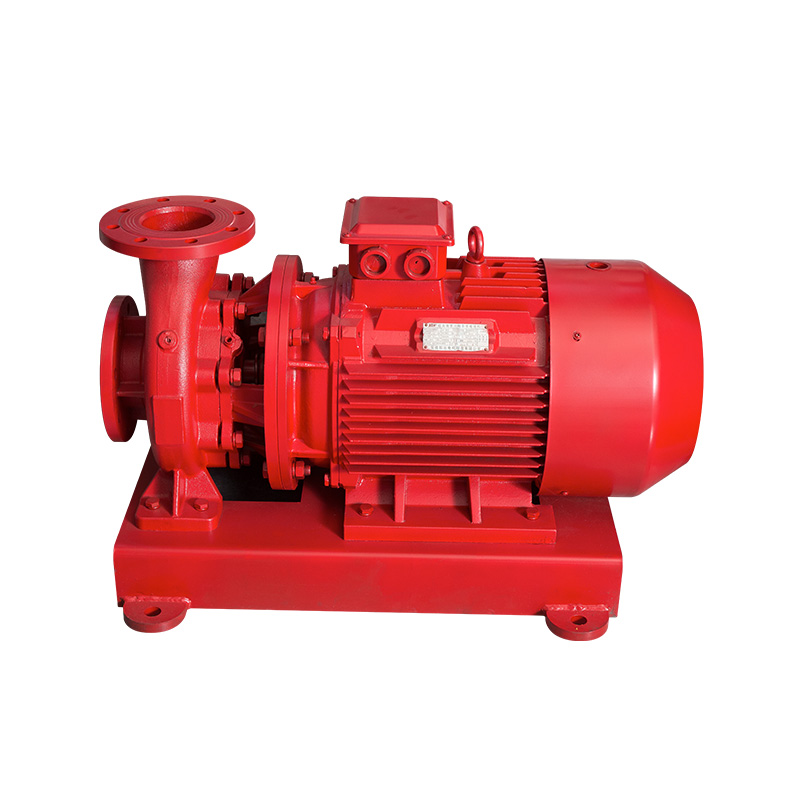
A horizontal pipeline pump is a centrifugal pump designed to be installed directly inline with a pipeline, with its shaft oriented horizontally and its suction and discharge flanges aligned on the same axis as the pipe. This in-line, axially aligned configuration means the pump can be bolted directly into a straight run of pipework without requiring 90-degree bends or offset connections, significantly simplifying installation and reducing the overall footprint of the pump assembly compared to end-suction or split-case centrifugal pumps mounted on a separate baseplate.
The operating principle follows standard centrifugal pump mechanics. An electric motor drives a shaft connected to a rotating impeller housed within a volute casing. As the impeller spins, it imparts kinetic energy to the fluid entering through the suction flange, accelerating it outward from the impeller eye to the periphery. The volute casing converts this velocity into pressure energy, and the pressurized fluid exits through the discharge flange into the downstream pipeline. Flow rate and head (pressure) output are governed by the impeller diameter, rotational speed, and the hydraulic characteristics of the volute and impeller design — all of which are summarized in the pump's characteristic curve provided by the manufacturer.
Horizontal pipeline pumps are available in single-stage and multistage configurations. A single-stage pump uses one impeller and is suited to applications requiring moderate head — typically up to 80 to 120 meters of water column depending on the design. Multistage horizontal pipeline pumps use two or more impellers in series, each adding incremental pressure to the fluid as it passes through successive stages. This allows multistage units to generate heads of several hundred meters while maintaining a compact inline form factor, making them the preferred choice for high-rise building water supply, boiler feed applications, and long-distance pipeline booster systems where a single stage would be insufficient.
Understanding the core specifications of a horizontal pipeline pump is essential for matching the equipment to the system's hydraulic requirements. Misinterpreting any of the following parameters is one of the most common causes of pump underperformance, premature failure, or energy waste.
| Specification | Typical Range | What It Governs |
| Flow Rate (Q) | 1 – 2,000+ m³/h | Volume of fluid delivered per unit time |
| Total Head (H) | 5 – 600+ m | Pressure energy added to fluid; system resistance overcome |
| Motor Power (P) | 0.37 – 500+ kW | Energy input required at design operating point |
| Efficiency (η) | 50% – 85% | Ratio of hydraulic output power to shaft input power |
| NPSHr (Required) | 0.5 – 8+ m | Minimum suction head needed to prevent cavitation |
| Speed (n) | 1,450 / 2,900 rpm (50 Hz) | Impeller rotational speed; affects Q, H, and noise |
| Flange Size (DN) | DN15 – DN300+ | Pipe connection diameter; determines installation compatibility |
| Maximum Working Pressure | 10 – 25 bar (standard) | Maximum allowable system pressure at pump casing |
Among these, Net Positive Suction Head required (NPSHr) deserves particular attention. If the available suction head in the system (NPSHa) falls below the pump's NPSHr, the fluid at the impeller inlet will partially vaporize, creating vapor bubbles that collapse violently as they enter higher-pressure zones — a phenomenon called cavitation. Cavitation causes erosive damage to the impeller and casing, generates significant noise and vibration, and sharply reduces pump performance. Always calculate the NPSHa for your system and confirm it exceeds the pump's NPSHr by a safety margin of at least 0.5 to 1.0 meters before finalizing a selection.
Understanding where horizontal pipeline pumps offer advantages — and where they do not — helps engineers and system designers make the most appropriate equipment choice for each application rather than defaulting to one pump type by habit.
| Pump Type | Installation Footprint | Maintenance Access | Best Application |
| Horizontal Pipeline | Minimal — inline with pipe | Good with back pull-out design | HVAC, water supply, booster systems |
| End-Suction Centrifugal | Requires baseplate and floor space | Excellent — open layout | Large flow, general industrial use |
| Vertical Inline | Compact — floor area only | Moderate | Where horizontal space is restricted |
| Split-Case Centrifugal | Large — requires dedicated pump room | Excellent — fully accessible internals | High-flow municipal and industrial use |
| Submersible | No above-ground space required | Poor — requires extraction to service | Groundwater, sewage, sump applications |
The horizontal pipeline pump's most distinctive competitive advantage is its inline installation geometry. Because the suction and discharge ports are coaxial with the pipe, the pump integrates seamlessly into an existing pipeline run without additional pipe bends, offset connections, or a concrete pump base. This reduces both installation labor and civil works cost, and it makes the pump particularly suited to equipment rooms, plant rooms, and mechanical spaces where floor area is at a premium.
The shaft seal is one of the most maintenance-sensitive components in any centrifugal pump, and horizontal pipeline pumps are no exception. The seal prevents process fluid from leaking along the rotating shaft where it exits the pump casing. Two principal sealing technologies are used in horizontal pipeline pumps: mechanical seals and gland packing.
Mechanical seals are the dominant choice in modern horizontal pipeline pump installations. A mechanical seal uses two precision-lapped, hardened face rings — one rotating with the shaft and one stationary in the housing — that press together under spring tension to create a fluid-tight barrier. High-quality mechanical seals using silicon carbide or tungsten carbide face materials offer long service lives of 20,000 hours or more in clean water service, with no routine adjustment required during operation. For pumping aggressive chemicals, high-temperature fluids, or liquids containing suspended solids, double mechanical seals with a pressurized barrier fluid provide an additional containment layer and significantly extend seal life in demanding conditions.
Gland packing — rings of braided fiber or PTFE compressed around the shaft by a gland follower — is a simpler and less expensive sealing method still found in older installations and some specific industrial applications where slight controlled leakage is acceptable. Packed gland seals require periodic manual adjustment to maintain acceptable leakage rates (a small controlled drip is required to lubricate the packing) and eventual repacking as the material compresses and wears. For clean, non-toxic fluid applications with infrequent maintenance intervals, gland packing remains a viable option, but mechanical seals are strongly preferred for new installations due to their lower leakage, longer maintenance intervals, and suitability for a wider range of fluid types.
The wetted components of a horizontal pipeline pump — casing, impeller, wear rings, and shaft sleeve — must be compatible with the fluid being pumped in terms of corrosion resistance, erosion resistance, and temperature capability. Selecting incorrect materials leads to accelerated wear, contamination of the fluid, and premature pump failure.
Even a correctly specified horizontal pipeline pump will underperform or fail prematurely if installed poorly. Following established installation guidelines from the outset protects both the equipment investment and the reliability of the system it serves.
Horizontal pipeline pumps are generally low-maintenance units, particularly when equipped with sealed-for-life motor bearings and cartridge mechanical seals. However, a structured inspection regime identifies developing faults before they result in unplanned downtime and costly emergency repairs.
Horizontal pipeline pumps offer a compelling combination of compact inline installation, broad application coverage, and straightforward maintenance when correctly specified and operated. Whether the application is a commercial building heating circuit, a municipal water booster station, or an industrial process cooling loop, matching the pump's hydraulic performance to the system curve, selecting appropriate materials and seal technology for the fluid service, and following sound installation practices are the foundations of reliable, energy-efficient long-term pump operation.

A vertical base is a pedestal used to support and secure a vertical TD...
See Details
The pump body consists of two main parts: suction chamber and pressure...
See Details
Stainless steel impeller material is stainless steel, it is not easy t...
See Details
1. Our WQ-type general sewage pump adopts a large flow channel anti-cl...
See Details
Installed on the upper part of the sewage pump unit, it is used for li...
See Details
Installed on the top of the sewage pump unit, it is used to enclose th...
See Details
Cast iron impeller is one of the key components of the pump, which pre...
See Details
A type of adjustable speed motor that can control the speed of the mot...
See Details
The stator of a motor refers to the fixed part which contains the stat...
See Details
1.TD horizontal high-efficiency and energy-saving circulation pump is ...
See Details+86-0563-2251312
+86-0563-2251311
+86-139 6620 0379
No.43 Guohua Road, Guangde Economic Development Zone, Xuancheng City, Anhui Province, China
